There's tons of info around the forum where people ask questions about how to connect up a period looking dash in their ReBody. Some threads on the topic just died out without a definitive answer.
So please allow me to start a thread specifically for questions about ReBody Dashboard Electrics.
I suppose my first question is what do you guys do with all the signals such as Seat Belts, Handbrake, ABS, DSC/ASC?
I don't fancy the idea of a load of little lights in the dash with stick on labels.
Make the dash look like a ransom note.

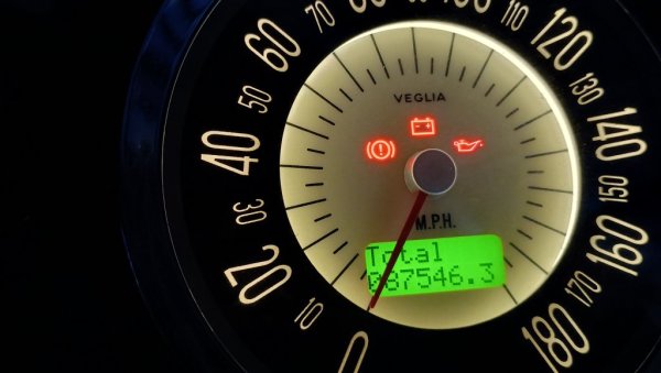
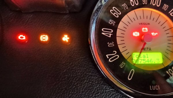
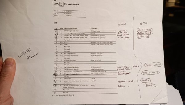
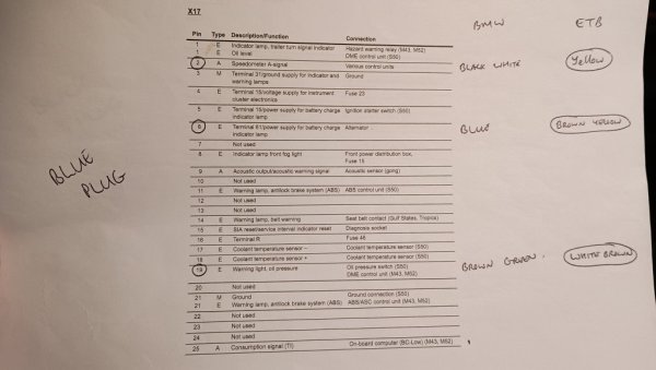
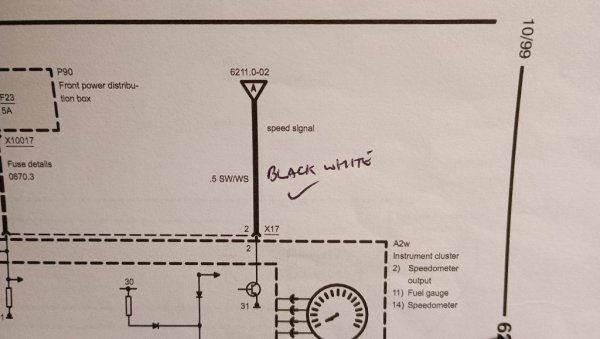
@Jezza In a thread last year you were asking about connecting up the various brake warning lights to one light in the speedo? I can see how that would work. Thank you for posting your findings re: wring colours. But did you ever get that working? What ETB Spedometer are you using? I can't see one on their website with built in warning lights. What did you do in the end? Please post a photo of the finished dash. Lit up?
Another thing I haven't fully got my head around is the instrument cluster. Leave it in there hooked up somewhere out of sight? I'd like to remove it if I could. Anyone managed that?
So, guys, did you do something in your dash that you think is different to what others have done? Please tell us what you did.
So please allow me to start a thread specifically for questions about ReBody Dashboard Electrics.
I suppose my first question is what do you guys do with all the signals such as Seat Belts, Handbrake, ABS, DSC/ASC?
I don't fancy the idea of a load of little lights in the dash with stick on labels.
Make the dash look like a ransom note.
@Jezza In a thread last year you were asking about connecting up the various brake warning lights to one light in the speedo? I can see how that would work. Thank you for posting your findings re: wring colours. But did you ever get that working? What ETB Spedometer are you using? I can't see one on their website with built in warning lights. What did you do in the end? Please post a photo of the finished dash. Lit up?
Another thing I haven't fully got my head around is the instrument cluster. Leave it in there hooked up somewhere out of sight? I'd like to remove it if I could. Anyone managed that?
So, guys, did you do something in your dash that you think is different to what others have done? Please tell us what you did.